On this page
Product specifications
Measurements
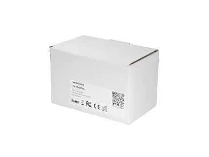
Measurements (box)
Specifications
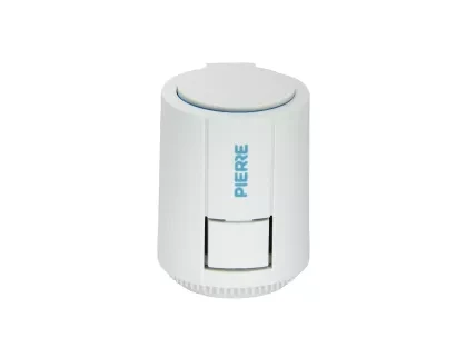
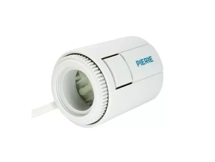
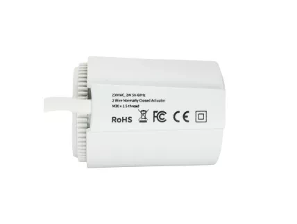
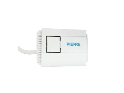
The PIERRE Pro Thermic Valve operates as a normally-closed (NC) unit, controlling the flow of heating or cooling within HVAC systems. Powered by a 230V input, the valve is engineered for long-term reliability and energy efficiency. The actuator is controlled by a thermal signal from the thermostat, allowing for precise temperature regulation in both residential and commercial environments.
Designed for seamless integration into modern heating systems, with very low consumption. Its robust construction and high operating voltage make it suitable for heavy-duty applications, delivering consistent performance in demanding setups.
UNIVERSAL CONNECTION INTERFACE: M30x1.5mm
Print user manual for Thermic Valve (NC, 230V)
- H: 52 mm
- W: 48 mm
Input Voltage
220-230V AC/24V
Consumption
2.50W
Panel material
ABS+PC material
Product color
White
Operating Temperature °C
-5°C - +60°C
Operating Temperature °F
+23°F - +140°F
Force
110N
Stroke
3.5-4mm
Running Time
3-5 minutes
IP
IP54
- Connect the 230V Live (L) wire to the relay module’s power input.
- Connect the Neutral (N) wire to the relay module’s neutral terminal.
- Wire the relay output (NO) to the Live input of the valve actuator.
- Connect the valve’s Neutral wire to the relay module’s Neutral terminal.
- Connect the relay module to the smart controller using control signal wires.
- Power the smart controller with a 12V DC power supply (connect +12V and GND).
- Link one controller output channel to a relay input to trigger switching.
- Ensure common GND is shared between controller and relay module.
Important: Install the device manually without using any tools; avoid pliers or sharp instruments to prevent damage to the components.
- Insert the mounting ring.
- Place the threaded mounting ring over the valve pin.
- Turn it clockwise to tighten it securely by hand.
- Attach the actuator.
- Align the device vertically with the valve.
- Press it down firmly onto the mounting ring until it clicks into place.
Take Down
- Press the release button.
- On the side of the device, press and hold the unlock button (or clip) while gripping the unit.
- Lift the device upward.
- While holding the release button, pull the device upward to detach it from the valve.
First-Time Activation
- Initial State (Locked – Factory Default):
- The actuator is locked and the valve is closed.
- No fluid flow is possible.
- A lock symbol indicates inactive status.
- Unlock by Powering On:Apply power to the actuator for at least 3 minutes.
- This unlocks the actuator and calibrates the internal mechanism.
- The valve temporarily opens during this phase.
- Power Off – Ready for Use:After the initial activation, remove power.
- The actuator returns to its normally closed state.
- A small visible gap of approx. 0.5 mm at the top confirms proper initialization.
After the first activation, verify that the actuator is in the correct position:
- Correct Position:
- A visible gap of approximately 0.5 mm between the actuator housing and the top cap indicates successful initialization.
- → Status: OK
- Incorrect Positions:
- If the top is completely flush with the housing – initialization may not have completed.
- If the top is raised too high – the actuator may be blocked or malfunctioning.
Action: If incorrect, repeat the first-time activation process by powering the actuator for 3 minutes.
- Power Cut (No Power):
- The valve remains closed by default.
- →Fluid or air cannot pass through the pipe.
Note: A "normally closed" actuator requires power to open. In its resting state (no power), the valve blocks the flow.
- Power On:
- When voltage is applied, the actuator opens the valve.
- → Flow is enabled, and the system operates normally.
Note: A "normally closed" actuator requires power to open. In its resting state (no power), the valve blocks the flow.
- Power Cut (No Power):
- The valve remains open by default.
- → Fluid or air can pass freely through the system.
Note: A "normally open" actuator closes only when powered. Without power, the valve allows continuous flow.
- Power On:
- When voltage is applied, the actuator closes the valve.
- → Flow is blocked, and the valve is shut.
Note: A "normally open" actuator closes only when powered. Without power, the valve allows continuous flow.
- Choose Controller
- Tap on the Controller that you would like to add new I/O to.
- To edit the I/O, click on the Controller to which the I/O is added.
- Outputs - Add button
- Tap on the Outputs at the top and tap on the button Add.
- Choose type - Outputs
- Tap on the type of the desired I/O that you would like to add.
- New Valve
- Fill following form:
- Name - Enter the name of the Valve.
- Role - Select the appropriate Role from the list.
- Group - Choose a Group from the list. Group is a group of I/Os and scenarios that seems most logical to you.
- Pin - Select the Pin, which is the physical location where the I/O connects to the Controller.
- Photo - Choose a photo for the Valve representing both the On and Off statuses.
- Slide to confirm - When enabled, you will be asked to confirm the desired operation to prevent accidental actions.
- Identifier - This field is the unique identifier for the I/O in the electrical project.
- Hide Activity - Use this option to conceal I/O activity from the Activity tab.
- Timeout - It is the duration of time the Valve will remain Open in auto mode.
- Once you have completed these entries, tap the Submit and Save to confirm your choices.
- Fill following form:
- Select Roles
- Tap in the field Role and after tap on the checkbox/checkboxes to select Role/Roles - multiple choice.
- Tap Save/Done.
- Select Groups
- In this step, you need to select one or more Groups.
- Select the checkbox/checkboxes next to the Group/Groups that you want to associate with the I/O.
- Once selected, the I/O will appear in the chosen Groups on the Dashboard.
- Tap Save/Done to confirm your selection.
- Change photo
- You have three sources for the picture:
- Open Library - It will open Library from your phone.
- Open Camera - You can take picture by your phone.
- Choose default image - Choose default image. These images are prepared in advance in order to provide a complete and seamless experience.
- When you want to confirm your choice tap button Done.
- You have three sources for the picture:
- Timeout - New Valve
- In order to set hours, minutes and seconds - to set Timer, you should scroll through each of these columns and when you are satisfied with your choice tap on Save button.
