On this page
Product specifications
Measurements
Measurements (box)
Specifications
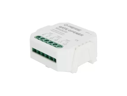
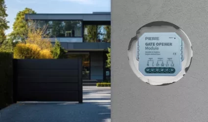
The PIERRE Wave Gate Opener Module operates on a 100-240V AC 50/60Hz power supply and is engineered to provide reliable control for gate and garage door systems. Utilizing the PIERRE Wave protocol, it seamlessly integrates with compatible smart home gateways, allowing users to manage their gate or garage doors remotely via the PIERRE Smart home system. This module is designed to work with motorized gates and garage doors, providing both secure access and automated operation.
The module offers voltage-free control, making it compatible with a wide range of gate and door mechanisms. Built-in overload and thermal protection features enhance the safety and durability of the system. Users can create custom schedules, automation rules, or integrate voice control commands to streamline entry and exit scenarios.
Print user manual for Gate Opener Module
- Reset Key
- Indicator Light
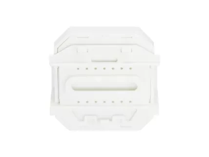
- Mounting Clip
- Without Mounting Clip
- W: 46 mm
- H: 46 mm
- D: 18 mm
- With Mounting Clip
- W: 50 mm
- H: 46 mm
- D: 22.5 mm
Power supply mode
100-240V AC 50-60 Hz
Connectivity
Zigbee
Operating frequency
2.4 GHz - 2.484 GHz
Wiring
N - Neutral, L - Line
Panel material
ABS+PC material
Product color
White
Number of channels
1 channel
Operation range
200m
LED Indicators
Yes
Operating Temperature °C
-10°C - +40°C
Operating Temperature °F
+14°F - +104°F
Operating Humidity % RH
≤ 80% RH
Safety features
Overload, Over Voltage, Short Circuit, Thermal Protection, Surge Protection, Static Protection
IP rating
IP20
Warnings:
- Installation must be carried out by a qualified electrician in accordance with local regulations.
- Keep the device out of reach of children.
- Keep the device away from water , damp or hot environments.
- Install the device away from strong signal sources such as microwave ovens that may cause signal interruption resulting in abnormal operation of the device.
- Obstruction by concrete wall or metallic materials may reduce the effective operation range of the device and should be avoided.
- Do NOT attempt to disassemble, repair or modify the device.
- Turn off the power supply before carrying out any electrical installation work.
- Connect wires according to the wiring diagram.
- Insert the module into the junction box.
- Turn on the power supply and follow dimmer module configuration instructions.
Note: Keep your smartphone close to the switch module during configuration.
The diagram illustrates the typical wiring configuration for the PIERRE Gate Opener Module. Each numbered component is described below:
- Input AC Power (L + N):
- The module is powered via a 100–240V AC input. Connect the Live (L) and Neutral (N) terminals as indicated. This powers the internal control and relay systems.
- Output – Contact Sensor (Relay Output):
- This dry-contact relay output is used to signal the garage door motor to open or close. It mimics the press of a manual pushbutton and connects directly to the garage door opener's control terminals.
- Fixed Contact Sensor Housing (Wall-Mounted):
- This part of the magnetic contact sensor is fixed to the wall or fixed frame. It remains stationary and aligns with the movable sensor element when the door is closed.
- Movable Contact Sensor (Gate/Door Mounted):
- The complementary part of the sensor, mounted directly on the gate or garage door. It moves with the door and completes the magnetic contact when aligned with the fixed sensor (3).
- Signal Terminals – L1 and L2:
- These terminals provide input for external control signals (e.g., from wall buttons or sensors). Note: Earlier diagrams may have mislabeled these as “S1/S2” — correct labeling is L1 and L2.
- Garage Door Motor Unit:
- Receives the relay signal from the module (via the contact output) and activates the motor to open or close the door accordingly.
- Manual Wall Pushbutton (Taster):
- A physical pushbutton connected to the L1 and L2 signal terminals. When pressed, it closes the circuit to simulate an open/close trigger for the gate motor.
The switch module terminal allows manual override access, enabling the end-user to turn the device on or off.
- Use the switch for a permanent on/off function.
Notes:
- Adjustments made via the app or the manual switch can overwrite each other. The last adjustment is saved in memory.
- App control is synchronized with the manual switch.
The PIERRE Wave system is a user-friendly solution for integrating and managing smart devices through a central platform. The system consists of the following components:
A - Required Elements:
- PIERRE Wave Products: These smart devices, including lighting, thermostats, sensors, and other appliances, connect wirelessly to the PIERRE Wave Gateway. They provide essential functions and capabilities for the system.
- PIERRE Wave Gateway: The central unit linking all PIERRE Wave devices, the gateway manages communication and data exchange, ensuring security and stability. It supports remote access and control, with the default Berlin display interface, though users can choose any PIERRE display model.
B - Optional Elements:
- Mobile PIERRE App: This app allows users to manage and monitor the system from their smartphone or tablet, offering real-time updates and remote access. It provides convenience but is not necessary for basic system operation.
- Router: An optional component that enables internet connectivity, allowing devices to be accessed and controlled remotely.
- System Operation: The gateway can connect to the router via Wi-Fi or LAN for internet connectivity, enhancing remote management capabilities. PIERRE Wave products communicate wirelessly with the gateway, which acts as the central hub. This bidirectional communication allows data to flow both ways, enabling users to send commands and receive status updates through the Mobile PIERRE App. The app facilitates effective management and real-time feedback on device statuses.
Please scan the QR code to download PIERRE application
Log in with you Username and Password
Open Settings and press "Add Wave I/O"
Press and hold the Reset Key for 10 seconds (use a small, thin object like a paperclip) until the Indicator Light starts flashing
- Indicator Light
- Reset Key
- PIERRE Wave Gateway
Press "Find Devices"
PIERRE application will show the list of available devices. Press "Add found devices"
Enter Name, Role and Group settings and Save it
When the Light indicator stops flashing, the PIERRE Wave pairing process is finished
Q1: What should I do if I can’t configure the switch module?
- Please check whether the device is powered on.
- Ensure you have a stable internet connection.
- Make sure the PIERRE Gateway is available.
- Make sure the wiring is correct.
Q2: What device can be connected to this PIERRE switch module?
It can be connected to devices such as gate opener, garage doors.
Q3: What happens if the WIFI goes off?
You can still control the device connected to the switch module with your traditional switch and with PIERRE Displays.
Q4: How do I reset the device?
Long press the reset key for about 10 seconds until the indicator light flashes quickly.


