On this page
Product specifications
Measurements
Measurements (box)
Specifications
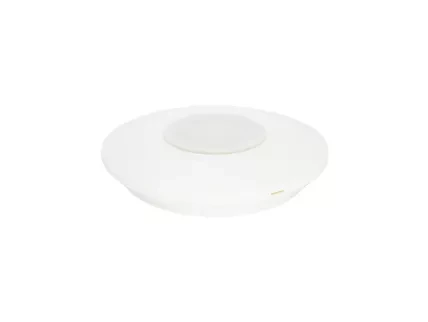
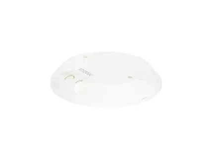
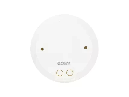
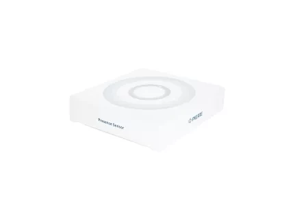
The PIERRE Pro Presence Sensor 360 operates on a 12-24V DC input and features a dry contact output for flexible integration with various control systems. Using radar-based detection technology at a working frequency of 5.8GHz, the sensor precisely identifies presence through minor motions such as breathing or hand movements, making it ideal for occupancy-based automation. Its versatile design includes adjustable detection areas to suit different room sizes and layouts, along with configurable hold times ranging from 5 seconds to 30 minutes.
This presence sensor incorporates an integrated daylight sensing feature with customizable lux levels or the option to disable it, allowing for energy-efficient lighting management. Designed for ceiling mounting, the sensor covers installation heights between 2m to 8m and maintains reliable performance in diverse lighting conditions. With a plane detection angle of 360°, it is suitable for various applications, including offices, conference rooms, and large commercial spaces.
Print user manual for Presence Sensor (Ceiling Mount)
- 23 mm
- 85 mm
- ∅ 105 mm
- 66 mm
- 65 mm
- ∅ 4,20 mm
- 15 mm
- ∅ 10,50 mm
Power supply mode
DC 12V/24V
Output
Dry contact, NO/NC
Frequency
5.8GHz ±75 MHz, ISM band
Product color
White
Installation Height
3.00m
Operating Temperature °C
-25℃ - +50℃
Operating Temperature °F
-13°F - +122°F
Operating Humidity % RH
85% (Non condensing)
Detection angle
360°
Detection Technology
Radar-based minor motion breathing
Detection area
100%/75%/50%/25%
Adjustable Features
Detection area / hold time / lux levels
Daylight Sensor
5lux/25lux/50lux/Disable
IP rating
IP20
Safety features
The terminal layout of a circular sensor or alarm base featuring four labeled connections: P1, P2, GND, and 12V.
- A 12V DC power supply is connected via the red wire to the 12V terminal, with a black wire to GND serving as the common ground.
- Terminals P1 and P2 are individually wired, likely intended for signal output or communication, such as dry contact signaling.
- Connect the +12V terminal of the sensor to the +12V output of the controller.
- Connect the GND terminal of the sensor to the GND terminal of the controller.
- Bridge the IN and +12V terminals on the sensor to enable the output switching logic.
- Connect the OUT terminal of the sensor to a digital input on the controller (e.g., INPUT 1).
- Daylight Harvesting
- Infrared Light
- Detection Area
- Hold Time
- Daylight Sensor
- Indicator Light
- Pilot Light
- Antenna Module
- P1
- P2
- GND
- 12V DC
- Insert a slotted screwdriver into the designated slot on the housing and gently pry to remove the cover.
Caution: Do not use excessive force. Use only insulated tools and follow local electrical safety regulations.
- Use a flat tool to gently lift the cover from the threading hole.
- When surface-mounted, the thin tab on the side of the housing should be removed to create a cable entry groove.
- Connect the wire to the terminal and configure the corresponding parameters as required.
- Secure the device to the designated mounting surface using a compatible screwdriver.
- Ensure the cover is securely fastened after installation, following the arrow indicator as a guide.
- Ceiling mount - 3m
- Breathing detection - 3m radius
- Micro Motion Detection - 4m radius
- Motion Detection - 4m radius
Signal detection: The sensor detects walking, slight movements (such as body shifts, head turns, and other minor actions), and breathing to identify human presence during a non-sleep state.
Movement signal: Large or noticeable movement that activates the sensor
Slight motion signal: When only very small body movements are detected, the indicator flashes once.
Breathing signal: When no slight motion is detected, only the breathing signal is collected. The indicator flashes three times after detecting three valid breathing signals.
When the ambient light is sufficient, the light will not turn on even if motion is detected.
When the ambient light is low, motion is detected and the light turns on automatically.
Movements like the body, head, and other small actions are detected during normal use, the light stays on continuously.
When the sensor fails to detect movement or slight motion, the light will automatically turn off after the set delay time
Detection Area
This section uses DIP switches 1 and 2 to set how sensitive the sensor is—i.e., how large the detection area is.
| |||
Hold Time
This section uses DIP switches 3, 4, and 5 to set how long the light stays on after motion is detected.
| ||||
| VII | ||||
| VIII |
Note: To enable the presence detection function (breath detection), the hold time must be set to at least 1 minute (preferably longer). The 5-second setting is intended for motion sensor testing only.
Daylight Sensor
This table shows how DIP switches 6 and 7 control the daylight (ambient light) threshold. This setting determines when the sensor is allowed to turn on the light, based on the surrounding brightness level
| ||||
Note: When set to "Disable", the sensor will turn on the light whenever it detects movement, regardless of the ambient light level.
Indicator light
This setting, DIP switch 8, controls whether the indicator LED on the sensor is ON or OFF
| ||
HS: The indicator light is on.
LS: The indicator light is off.
Note: The indicator is ON by default. It can be turned OFF using the DIP switch or by pressing the LS button on the remote control.
When powered on for the first time, the sensor enters a self-test mode. This process lasts for 20 seconds, after which the sensor switches to normal operation.
During initialization, external motion signals are not detected, and remote control signals are ignored.
- Indicator Light: On
- Detection Area: 100%
- Hold Time: 1 minute
- Daylight Sensor: Disabled
- Professional Installation Required:
- The sensor must be installed by a qualified electrician. Always disconnect the power before installation, wiring, or changing the dial (DIP) switch settings.
- Avoid Interference from Dense Materials:
- Keep the sensor away from large areas of metal, glass, or other high-density materials to prevent false triggering.
- Avoid Constant Vibration Sources:
- Do not install the sensor near objects that vibrate continuously (e.g. oscillating fans), as vibrations may be detected as motion and cause false triggers.
- Remote Control Feedback:
- The indicator light will flash three times quickly to confirm successful remote control settings.
- Initialization Limitations:
- During initialization (first 20 seconds after power-on), sensing functions are disabled, and sensor parameters cannot be set via remote control.
- Indicator Light Recommendation:
- It is recommended to turn off the indicator light during normal use to save power or reduce distraction.
- Hold Time Recommendations by Room Type:
- In open offices with many people: 30 seconds
- In private offices or smaller spaces: 1 minute or more (ideally 3 minutes or more)
- Microwave Penetration Warning:
- The sensor's microwave signal can penetrate walls. If the signal reaches outside the intended detection zone, it may trigger due to movement outside.
- To avoid false alarms:
- Avoid installing near materials that microwaves can easily pass through (glass, plasterboard, wooden walls).
- Choose proper installation locations and detection settings based on the room size:
- Detection Area Recommendations:
- Room size ~2m x 2m → Set detection area to 25%
(e.g., washroom, small sitting area) - Room size ~3m x 3m → Set detection area to 50%
(e.g., hallway, medium sitting area) - Room size ~4m x 4m → Set detection area to 75%
(e.g., small office, meeting room, library) - Room size ~5m x 5m or larger → Set detection area to 100%
(e.g., large office, conference room, open library)
- Room size ~2m x 2m → Set detection area to 25%
Note: Detection area settings should be adjusted according to the actual environment. The above examples are for reference only.
- Hold Time Settings Based on Occupancy:
- For single-person spaces: Set hold time between 1–3 minutes
- For multi-person spaces: Set hold time between 30 seconds to 1 minute
- Avoid setting hold time above 5 minutes, as it may cause small movements to continuously reset the timer and prevent the light from turning off.
