On this page
Product specifications
Measurements
Measurements (box)
Specifications
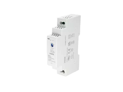
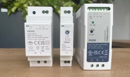
The PIERRE Pro Power Supply operates with a 100-240V AC input and delivers a stable 12V DC output at 1.25A, with a maximum power of 15W. It efficiently converts AC to DC, providing the essential direct current required for powering smart home devices and automation components. The wide input voltage range ensures compatibility with global power grids.
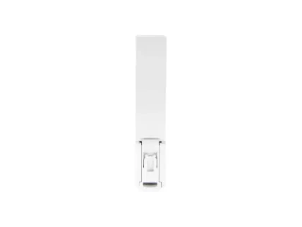
The DIN rail compatibility allows for easy installation into electrical cabinets, making it an ideal solution for powering smart home systems. Engineered for high reliability, it provides stable and efficient power delivery, ensuring long-term performance in demanding environments.
Print user manual for Power Supply 12V/1.25A 15W (DIN)
- H: 90 mm
- D: 58 mm
- W: 18 mm
Input
100-240VAC
Output
12.0V DC, 1.23A, 15W
Efficiency
85%
Current
1.20A
Power Factor (Pf)
0.98
Connectivity
Zigbee
Wiring
N - Neutral L - Line
Operating Temperature °C
-20°C ~ +70°C
Product color
White
Mounting
DIN Rail
LED Indicators
Yes
Operating Temperature °C
-4°C ~ +158°C
Operating Temperature °F
-4°F ~ +158°F
Operating Humidity % RH
20% - 90% RH, Non Condensing
Storage Temperature °C
-40°C - +80°C
Storage Temperature °F
-40°F - +176°F
Safety features
Overload, Over Voltage, Short Circuit
IP rating
IP20
- Connect the AC input terminals to mains power: L (Live) and N (Neutral).
- The power supply converts AC to 5V DC, with outputs labeled +5V and GND.
- Connect +5V to the device’s VCC input, and GND to its GND input.
- Use proper gauge wires and double-check polarity to avoid damaging connected devices.
Functional Diagram – System Overview
The diagram illustrates the internal functional structure of a standard switching mode power supply (SMPS). This block diagram provides a high-level representation of the main operational stages from AC input to regulated DC output.
Block Descriptions:
- I/P (Input):
- AC mains voltage is supplied to the power supply.
- EMI Filter:
- Attenuates conducted and radiated electromagnetic interference to meet EMC compliance and protect downstream components.
- Rectifiers & Filter (Primary Side):
- Performs AC to DC conversion and smooths the rectified voltage using capacitive filtering.
- Power Switching Stage:
- A high-frequency switching converter (typically using a MOSFET) chops the DC voltage to drive the transformer. Switching is controlled via PWM (Pulse Width Modulation) for efficient power regulation.
- Transformer:
- Provides galvanic isolation between input and output and adjusts the voltage level through step-up or step-down conversion.
- Rectifiers & Filter (Secondary Side):
- Converts the high-frequency AC from the transformer back to DC, followed by filtering to reduce ripple and noise. Delivers dual output rails: +V and –V.
- Detection Circuit:
- Monitors output voltage levels and generates feedback for regulation. Ensures output remains within defined tolerances under varying load conditions.
- Control Circuit:
- Core of the regulation system. Processes feedback signals and adjusts the switching duty cycle accordingly. Ensures stable and accurate DC output.
- O.L.P. (Over Load Protection):
- Detects overload or short-circuit conditions on the output. Limits output current or shuts down the converter to prevent thermal damage.
- O.V.P. (Over Voltage Protection):
- Monitors output voltage and disables the power supply if voltage exceeds predefined limits, protecting connected loads.
- Load (%)
- Ambient Temperature (°C)
- Load (%)
- Input voltage (VAC) 60Hz


