On this page
Product specifications
Measurements
Measurements (box)
Specifications
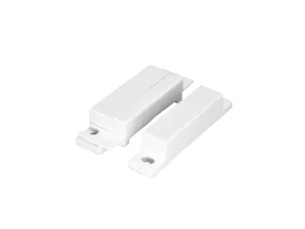
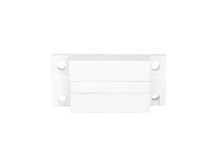
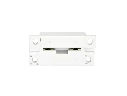
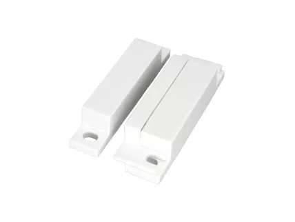
The PIERRE Pro Magnetic Contact Sensor is designed for enhanced smart home security, featuring precise monitoring of entry points. The sensor operates through direct alarm circuit integration, providing reliable detection through proven magnetic contact principles. It uses standard NC (Normally Closed) configuration to ensure stable connectivity and reliable integration within security networks. With built-in circuit continuity monitoring, it actively detects any potential tampering or interference.
Constructed with durable ABS plastic, its surface-mount design allows for quick and secure installation on various door and window types, making it an essential component for security systems. The device integrates directly with PIERRE Smart home systems through standard alarm inputs, enabling real-time monitoring and alerts, ensuring consistent entry point detection for comprehensive security implementations.
Print user manual for PIERRE Pro - Magnetic contact sensor
- D: 13mm
- H: 12mm
- W: 62 mm
Power supply mode
DC 12V
Output
NC contact type
Current
0.20A
Panel material
ABS plastic
Product color
White
Operating Temperature °C
-20°C ~ +80℃
Operating Temperature °F
-4°F - +176 °F
Alarm triggering distance
20.00mm
Safety features
Tamper alarm, Disconnection alarm, Door status detection
- Connect the COM terminal of the sensor to a +12V supply.
- Connect the NO (Normally Open) terminal to a digital input on the controller (e.g., IN1).
- Connect the GND terminal of the controller to the sensor's ground line to complete the circuit.
- Choose Controller
- Tap on the Controller that you would like to add new I/O to.
- To edit the I/O, click on the Controller to which the I/O is added.
- Add button for Inputs
- Inputs tab is selected.
- List of Inputs is shown.
- In order to add new Input tap on the Add button.
- Choose type - Inputs
- From the list that is shown tap on the desired I/O that you would like to add.
- New Magnet Contact sensor
- Fill the following form:
- Name - Write the name of the Magnet sensor.
- Role - Choose Role from the list.
- Group - Choose Group from the list. Group is a group of I/O and scenarios that seems most logical to you.
- Pin - Choose Pin from the list. Pin is physical place on the Controller where I/O is connected to it.
- Photo - Choose photo for the Magnet sensor.
- Identifier - This field is the identifier of the I/O in the electrical project.
- Advanced - You can choose type of the signal that activates or tiggers the Magnet sensor: rising, falling, change, change inverted.
- Timeout - It is the duration for which the Magnet Contact sensor will remain Open in auto mode.
- When you want to confirm your choice tap Save and Submit.
- Select Roles - Inputs
- Tap in the field Roles.
- Select checkbox/checkboxes (for multiple choice) next to the Role/Roles that you would like to choose.
- To confirm selection tap the button Save/Done.
- Select Groups - Inputs
- In this step you should select Group.
- Select check box/check boxes next to the desired Group/Groups from the list.
- When you want to confirm your choice tap button Done/Save.
- Change Photo
- Tap on the photo of the Magnet Contact sensor.
- You have three options:
- Open Library - The phone’s Library will open.
- Open Camera - You can take a picture using your smartphone.
- Choose default image - These images are prepared in advance in order to provide a complete and seamless experience.
- Choose PIn
- Tap on the radio button next to the Pin that you would like to choose.
- To confirm selection tap on Save/Done.
- Advanced - Magnet Contact sensor
- Tap radio button next to the type of signal that you would like to choose.
- You can choose:
- Rising
- Falling
- Change
- Change inverted
- You can choose type of the signal that activates or triggers the Magnet Contact sensor.
