On this page
Product specifications
Measurements
Measurements (box)
Specifications
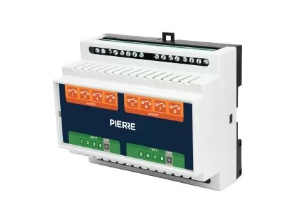
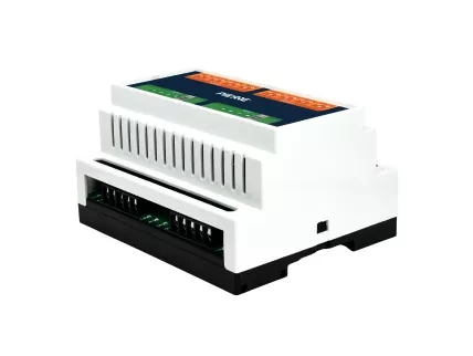
The PIERRE Pro Relay Board 8ch allows efficient switching of multiple high-power devices such as lights, motors, and appliances. Each relay channel supports a load capacity of up to 2.5A, with clear labels for inputs and outputs to simplify installation.
The board features reverse polarity, over-voltage, and short circuit protection to ensure safety. It operates with a 12V DC input and is designed to fit standard DIN rail mounts, enabling easy integration into control systems. Built with durable PCB materials, the board ensures reliable performance in various environments.
The PIERRE Pro Relay Board 8ch using solid-state relay (SSR), an electronic switching device that uses semiconductor components (such as triacs, thyristors, or transistors) instead of mechanical contacts to switch a load on or off.
Short Technical Description:
A solid-state relay works by receiving a low-power control signal (typically DC), which activates an optocoupler (opto-isolator). The optocoupler provides galvanic isolation between the control and load sides. When triggered, the internal semiconductor switch (like a triac for AC loads) conducts, allowing current to flow through the load. When the control signal is removed, the device stops conducting.
Key Characteristics:
No moving parts → silent and durable
Fast switching
Electrical isolation between input and output
Low control voltage with capability to switch high-voltage loads
Print user manual for Relay Board 8ch
- Housing
- Relay Outputs
- Input Terminals
- Input Ground (GND)
- W: 105 mm
- D: 58 mm
- H: 86 mm
Input Voltage
12V DC
Input
8
Output
8
Current
0.01A
Product color
White
LED Indicators
Yes
Operating Temperature °C
0°C - +50°C
Operating Temperature °F
+32°F - +122°F
Operating Humidity % RH
10% - 95% RH (non-condensing)
Altitude
<3000m
Safety features
Overload, Over Voltage, Short Circuit, Reverse polarity
Panel Material
PCB substrates
- Connect +12V to the relay module and the main controller.
- Connect GND to the relay module and the main controller (common ground).
- Connect RS485 A/B (or data lines) between the controller and the relay module.
- Connect Live (L) to the COM terminal of each relay output.
- Connect the NO (Normally Open) terminal to the load (e.g. light, motor).
- When the relay is activated, power flows from COM to NO to energize the load.
-
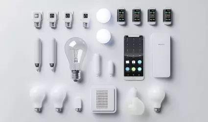
Compatible Light Devices
-

Light control
-

Garage Door Control
-
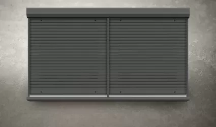
Blinds Control
-
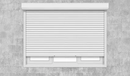
PIERRE Blind Motors
-

Curtains Control
-

HVAC with blower speed
-

Magnetic/Motorized Valves
-

Irrigation Valve
-

Fan/Motor
-
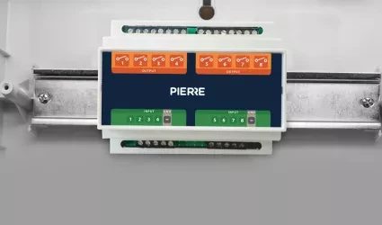
PIERRE Relay Board 8
-

Water Heater
-

Sauna
-

Pool
-

Hot Tub with Massage Jets
-
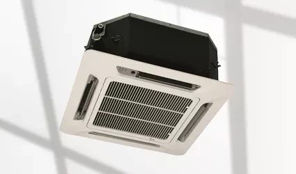
Fan Coil
-

Recuperator
-
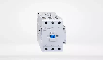
Contactor
-

Pergola Control
-

Valve
