On this page
")
Product specifications
Measurements
Measurements (box)
Specifications
The PIERRE Springfield Intercom is engineered with dual power options, accommodating both DC 24V and PoE 48V, ensuring flexibility in deployment across various installations. It integrates a 2MP CMOS camera equipped with a 2.2mm focus length lens, providing a diagonal field of view of 95° for comprehensive surveillance coverage. The camera angle can be adjusted by 12° in all directions, optimizing the device's placement and coverage area.
The white fill-in light enhances visibility under zero-lux conditions, ensuring reliability in low-light environments. Designed to handle challenging conditions, the intercom operates efficiently with a maximum current draw of 300mA, maintaining a low static current of 75mA in PoE mode. This rugged construction and adaptive power configuration make it a reliable solution for secure access control in various residential and commercial settings.
Print user manual for PIERRE Intercom Springfield (1 Button)

H: 19,3 cm
W: 12 cm
D: 4 cm

- Camera
- Fill Light
- MIC
- Card Reader Area
- Name Tag
- Speaker
- Call Button

- Mounting Hole
- Used to secure the device to the wall with screws or fasteners.
- I/O Terminal Block
- This terminal block is used to connect various external devices. Pin functions typically include:
- Unlock / NO / COM / NC – Relay output for electric lock control
- GND – Ground
- GS – Door sensor input
- EL – Additional lock or auxiliary output
- +24V / GND – Power input (24V DC)
- Power Input
- A dedicated 2-pin terminal for connecting the 24V DC power supply.
- +24V – Positive voltage
- GND – Ground
- RJ45 Port (Communication)
- Used for data communication, often via RS-485 or a proprietary bus.
- TX / RX – Transmit and receive lines for serial communication
- May be used to connect to other indoor/outdoor panels or control systems.
Power supply mode
DC 24V / PoE 48V
Consumption
0.30W
Over Voltage Range
12V DC - 15V DC
Current
0.30A
Static current
≤75mA (PoE 48V)
Connectivity
10M/100M Ethernet RJ45
Panel material
Metal
Product color
Grey
Mounting
Wall
Installation Height
1.60m
LED Indicators
Yes
Power over Ethernet (PoE)
Yes
PoE protocol
IEEE 802.3af/at 15.4W/30W
Operating Temperature °C
-20°C ~ +70°C
Operating Temperature °F
-4°F ~ +158°F
Safety features
Tamper alarm, Disconnection alarm, Door status detection
Camera - Sensor Type
CMOS
Resolution
2MP
View Angle
Diagonal 95°
Focus Length
2.2mm
Minimum Illumination
0 lux
Fill-in Light
White LED
Adjustable Angle
12° (up/down/left/right)

Recommended Installation Height: 1.6 meters - 5.25 feet
H: 1.60 m - 5.25 feet

Installation Steps
Embedded Box Dimensions
- Width: 100.6
- Height: 175.5
- Depth: 39 mm

Step 1: Prepare the Wall Slot for the Embedded Box
Cut a slot in the wall that matches the dimensions of the embedded box (100.6 × 175.5 × 39 mm). Ensure the slot is level and deep enough to securely hold the box.

Step 2: Install the Embedded Box
Place the embedded box into the prepared wall slot, ensuring it fits securely. Align it properly, then fasten it using screws to fix it firmly in place.
- Holder
- Wall
- Embedded Box
- Screws

PIERRE Springfield Intercom Wiring-hybrid (PIERRE Controller and Intercom)
This diagram shows the wiring connections for the mini outdoor station. Below are the main interfaces and their functions:
- Power Input (+12V / GND): Connect to a 12V DC power supply.
- Lock Control (LOCK1 / LOCK2): Relay outputs for controlling electric or magnetic locks.
- Exit Button (EXIT): Connect an internal button to unlock the door from inside.
- Alarm Output: Triggers external alarms on tamper or configured events.
- LAN Port (RJ45): Connects the device to the local network or server.
- Wiegand Interface (WG IN/OUT): For integration with external access control readers (26/34-bit).
- RS485 Port (A/B): For communication with external devices like controllers or sensors.
Note: Always wire with the power off. Installation should be done by qualified personnel.

PIERRE Springfield Intercom Wiring Gate/Door opening by Intercom
This diagram shows the external wiring setup for connecting the mini outdoor station to various peripherals and systems:
- 12V Power Supply: Provides power to the device.
- LAN Port: Connects the device to the local network.
- Electric Lock Terminals (LOCK1 / LOCK2): For controlling one or two door locks.
- Exit Button: Allows door unlock from inside.
- Door Sensor: Detects door open/closed status.
- Alarm Output: For external siren or warning light connection.
- Wiegand / RS485 Ports: For third-party access systems or integration.
Note: Ensure all connections follow polarity and voltage specifications. Only qualified installers should perform wiring.

PIERRE Springfield Intercom Wiring Gate/Door opening by PIERRE Controller
This diagram illustrates how the mini outdoor station integrates with a door access system:
- Power Input (12V DC): Powers the device.
- LAN Connection: Connects to the building's network for communication with indoor monitors or the server.
- Exit Button and Door Sensor: Allows users to exit and tracks door status (open/closed).
- Electric Lock Output: Controls the locking mechanism.
- Alarm Output: Connects to a security alarm for tamper or door-related alerts.
- Integration Ports (RS485 / Wiegand): For connecting external access controllers or card readers.
Note: Always ensure proper voltage and secure connections. Installation must be performed by qualified personnel.
The PIERRE Intercoms are SIP-based, operating on the "offline-first" principle. This means that the system initially establishes a connection through the local network. If internet access is available, remote access becomes possible. For SIP-based systems, a dedicated server is not strictly necessary.
A network router is a fundamental and essential component of the PIERRE door entry system. The modem-router provided by internet service providers is suitable for this purpose.
The router must be configured with a DHCP server range depending on the size of the project.
Example:
For a residential building with 50 apartments:
- Router IP address: 192.168.1.100
- IP addresses for the internal units of the Pierre door entry system in apartments:
- Apartment 1: 192.168.1.1
- Apartment 6: 192.168.1.6
- Apartment 50: 192.168.1.50
- The DHCP server IP range to be configured on the router: 192.168.1.101 - 192.168.1.254
Role Setup
PIERRE intercom has to be added to the Common controller on separate role.
Every apartment has to have access to the intercom and the appropriate door to unlock with the intercom. Intercom and door has to be on a separate role called Intercom and excluded from the default Role. This new role, called Intercom, must be added to the PIERRE displays (intercom's indoor unit) and to those users who we want to be able to ring the intercom.
Every PIERRE Display Requires a Fixed IP Address
For optimal functionality and reliable performance, all PIERRE displays must be assigned a fixed IP address. This ensures seamless communication and avoids potential conflicts within the network.
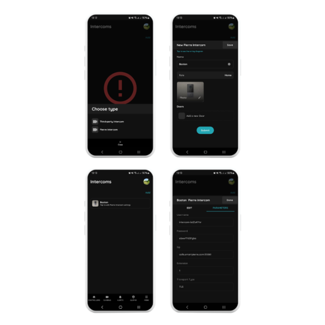
Menu - Intercoms - Add
Select the PIERRE Intercom
Choose the PIERRE Intercom from the available options.
Configure the Intercom Settings
- Name: Enter a custom name of your choice.
- Role: Select the appropriate role for the intercom.
- Doors: Specify which doors can be opened via the intercom.
Save the Configuration
After saving, click on the newly created intercom to view or modify its settings.
Access Parameters
Navigate to the Parameters tab to find the configuration settings for the Pierre Intercom. These settings are automatically generated by the system and can be adjusted as needed.
- Default Network Configuration: DHCP
- By default, the Pierre Springfield intercom obtains its IP address from the DHCP server (managed by your router).
- Connect to the Network
- Connect to the network by Wi-Fi or Ethernet with your notebook-computer.
- Scan the network using an IP scanner (e.g., Angry IP Scanner) to identify the intercom’s assigned IP address.
- Access the Intercom’s Web Interface
- Open a web browser and enter the identified IP address.
- Default login credentials:
- Username: admin
- Password: admin
Important: Change the default login credentials at the end of the setup process and record the new details securely.
In the intercom’s web interface, set up the following parameters under SIP Account Settings:
- Username: Enter the extension from the PIERRE Partner application.
- User Name 1: Use the username from the PIERRE Partner application.
- Server Password: Enter the password from the PIERRE Partner application.
- Server Address: Input the server address provided by PIERRE Partner application.
- Server Port: Set to 55061.
- Transfer Mode: Select TLS (Transport Layer Security).
- Navigate to Address Book under Contact Settings.
- Add a contact:
- Remark: Provide a name (e.g., Apartment 1, John Doe).
- SIP: Enter the SIP address in this format:
sip:1@display-ip-address
- Configure the Call Behavior:
- Short Press: Assign the contact from the address book to the button’s short press.
- Long Press: Assign the same contact for the long press.
- Save the settings and test the functionality to ensure the intercom calls the intended recipient when the button is pressed.
Step 1: Access Network Settings
- On the display, pull down the status bar from the top of the screen.
- Connect the Pierre display to the internet using a Wi-Fi network (this is optional and not required for door intercom functionality).
- Use Ethernet for internal network communication of the intercom system.
Step 2: Configure Ethernet for Internal Communication
- Use Ethernet for internal network communication with the intercom system.
- Navigate to IP Settings and select Static.
Step 3: Assign Fixed IP Address
- IP Address:
- Assign a fixed IP address that is outside the DHCP range to avoid conflicts.
- Gateway:
- Enter the IP address of the network gateway (typically the router’s IP address).
- Subnet Mask:
- Configure the appropriate subnet mask (e.g., 255.255.255.0 for most networks).
- DNS:
- Set the domain name server (DNS) as required by the network.
Step 4: Router Configuration
- Ensure the router manages IP distribution for all devices on the network.
- The display’s IP address must remain outside the DHCP range.
Example Configuration for Smaller Projects (Up to 45 Apartments):
- Router DHCP Server Start Address:
- Set the DHCP server to start distributing IP addresses from, e.g., 192.168.1.100.
- Static IP Range for Displays:
- Assign static IPs below the DHCP range, e.g.:
- Display for Apartment 1: 192.168.1.1
- Display for Apartment 6: 192.168.1.6
- Display for Apartment 45: 192.168.1.45
- Assign static IPs below the DHCP range, e.g.:
By following these steps, the intercom system will function seamlessly, avoiding IP conflicts and ensuring reliable communication across the network.
Calling the Indoor Station / Management Center
Prerequisite:
Ensure the target device (Indoor Monitor or Guard Unit) has been configured as the called party using the configuration tool.
Operation:
- The user can press the call button either short or long depending on the desired function.
- The mini outdoor station will initiate a call to the Indoor Monitor or Management Center (Guard Unit) as configured.
- A ringback tone will be played during the call attempt.
- If the call is not answered within 30 seconds, it will be automatically terminated.
During the Call:
- The Indoor Monitor or Guard Unit can remotely unlock the door.
- They can also take a screenshot for recordkeeping or security purposes.
Unlock
The mini outdoor station supports multiple unlocking methods. Each successful unlock action generates an unlock record for security tracking.
- IC Card Unlock
- Swipe a registered IC card at the card reader area on the outdoor station. The door will unlock, and an unlock record will be created.
- Indoor Monitor Unlock
- During a call or while monitoring the mini outdoor station, residents can unlock the door directly from their indoor monitor. This action also generates an unlock record.
- Exit Button Unlock
- An exit button can be connected to the designated interface on the outdoor station. Residents inside the building can press the button to unlock the door. This action will also be recorded.
- Management Center Unlock
- If properly configured, the management center can unlock the mini outdoor station by clicking the Unlock All button and entering the management password. This operation creates an unlock record.
- App Unlock
- Users can unlock the door via the mobile app by selecting the device in the app's device list. An unlock record is generated by the outdoor station.
Note: To unlock via the app, the following conditions must be met:
- The outdoor station must be bound to the community platform via the configuration tool using the correct Community ID.
- The user's app account must be bound to the platform and approved through personnel verification.
- The app account must have access control permission for the mini outdoor station.
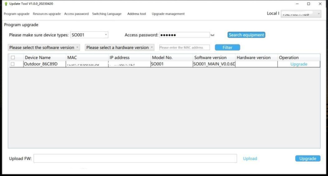
Follow the steps below to configure the mini outdoor station using the configuration tool:
Step 1: Launch the Configuration Tool
- Run the program named “WpfAppUpdate” as an administrator.
Step 2: Switch Language (Optional)
- Select your preferred language from the language options in the tool.
Step 3: Device Search
- Set the Device Type to "SO001".
- Enter the Access Password: 801801.
- Click "Search Equipment" to locate the device.
- Identify the device using its MAC address and corresponding IP address.
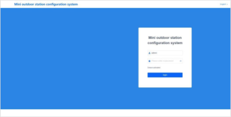
Step 4: Access the Web Configuration Page
- Open a web browser and go to: http://192.168.151.5/#/
- Log in using the default username and password:Username: (not required)
- Password: admin
Important Note:
Ensure that the computer's IP address and the device's IP address are on the same network segment to allow successful communication and configuration.
Device Name
The device name can be modified to suit your system configuration.
If you intend to use SIP account information from the address book, the device name must match the name associated with the SIP account in the address book.
After entering the device name, the system will prompt you with a pop-up window asking whether to use the corresponding account information from the address book.
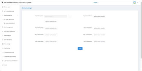
Call Setting
This setting allows you to configure the called party for the button on a single outdoor unit.
- Click the “Address Book Selection” button.
- In the pop-up window, select the contact(s) to be called when the button is short-pressed or long-pressed.
- Each button can be assigned up to 8 contacts.
This enables flexible calling behavior depending on how the button is used.
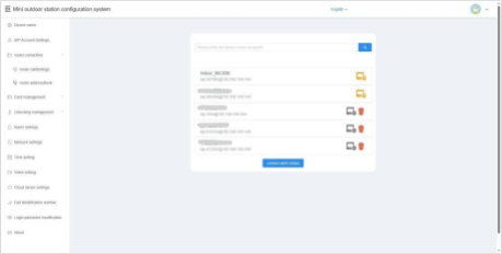
Contacts List
This section displays information about all current contacts. Contacts may include:
- Network devices discovered automatically when automatic configuration is enabled
- Devices imported from the address book
- Manually added devices
Add
You can add a new contact to the local device by entering the following information:
- Remarks (display name)
- SIP Account
Delete
You can delete contact entries from the list.
Note:
- Online network devices discovered through automatic configuration cannot be deleted.
- Devices imported from the address book are also not deletable.
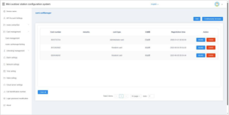
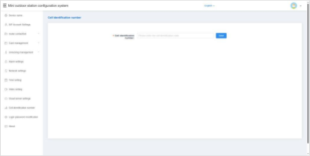
Use the configuration tool to register, modify, delete, or clear access card information on the local device.
In default server or custom server mode, card data is automatically synchronized with the platform. The device supports up to 20,000 access cards.
Single Addition
- Enter the card number manually or place the IC card near the card reading area of the mini outdoor station to automatically read the card number.
- Select the card type:
- User Card
- Administrator Card
- Click Confirm to complete the registration.
Continuous Addition
- Select the desired card type.
- Swipe each IC card over the card reader one by one.
- A beep will indicate each successful registration.
- Repeat the swiping process to register multiple cards in sequence.
Modification
- Click the Modify button in the action bar to update access card details.
Deletion
- Click the Delete button in the action bar to remove an access card.
- Once deleted, the card will no longer have permission to unlock the device.
Empty
- Clears all user and administrator card data from the device.

Card Anti-Copy
When this option is enabled, all newly registered access cards will be encrypted, making them non-copyable. This enhances security by preventing unauthorized duplication of cards.
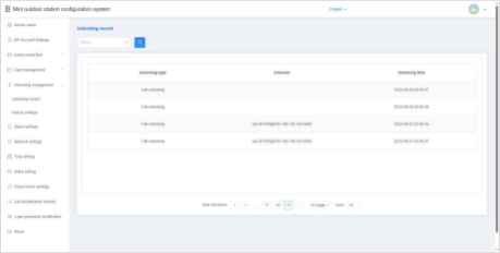
Unlocking Records
This feature allows you to view the unlock history of the device. Each record includes details of the unlocking method, time, and user or device involved, providing a clear audit trail for security monitoring.
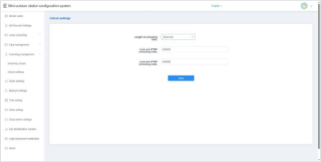
Unlocking Setting
Unlocking Time
You can configure the duration the door remains unlocked after an unlock command is issued.
- The time range is 1 to 30 seconds.
- After the set time elapses, the door will automatically re-lock.
Lock 1 / Lock 2 DTMF Unlock Password
Set the DTMF unlock password for Lock 1 and Lock 2.
- Default passwords:
- Lock 1: 666666
- Lock 2: 888888
- When the DTMF password set on the outdoor station matches the password on the indoor unit, the door can be unlocked via DTMF signaling.
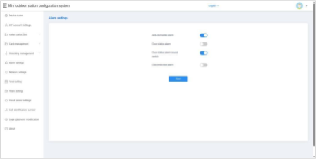
Tamper Alarm
When enabled, the device will sound an alarm tone if it is physically tampered with or removed by external force.
Disconnection Alarm
When enabled, the device will emit an alarm tone if it becomes disconnected from the network.
Additionally, a disconnection icon will appear in the status bar.
Door Status Alarm & Alarm Tone
When enabled, if the door remains open for more than 120 seconds, the device will trigger an alarm tone to alert users of the abnormal door status.
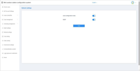
Automatic Configuration Mode
When enabled, the device can automatically discover other S-series devices within the same network segment. This simplifies device integration and communication.
DHCP
When DHCP is disabled, you must manually configure the network settings. Enter the following parameters:
- IP Address
- Subnet Mask
- Gateway
- DNS Server
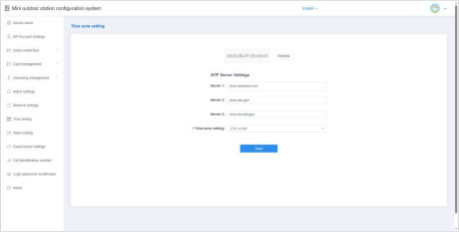
Refresh
After modifying the NTP server or time zone settings, click Save, then click Refresh. This allows the device to update and synchronize its local time with the configured settings.
NTP Server Setup
Enter the address of an NTP (Network Time Protocol) server to enable the device to automatically obtain accurate clock time.
Time Zone Setting
Select the appropriate time zone based on your country or region. The device will adjust the local time according to the selected time zone and the NTP server data.
This option allows you to configure the video bit rate used during calls and monitoring. Adjusting the bit rate helps balance video quality and network performance based on your specific environment and bandwidth availability.
This option allows you to change the login password used to access the device’s configuration interface.
It is recommended to set a strong, secure password to protect the device from unauthorized access.
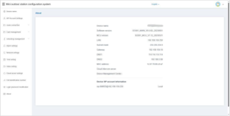
The About section provides detailed information about the device, including:
- Device Name
- Software Version
- MCU Version
- LAN IP Address
- Subnet Mask
- Gateway
- DNS Server
- MAC Address
- Cloud Intercom Server
- Device Management Center
- SIP Account Information
This information is useful for network configuration, troubleshooting, and technical support.


